
Basic IP Addressing and Troubleshooting Guide:
The purpose of this document is to provide a basic overview of IP addressing and routing as well as some troubleshooting tips to use when performing initial setup of a router.
Like other network layer protocols, the IP addressing scheme is integral to the process of routing IP data through an internetwork.
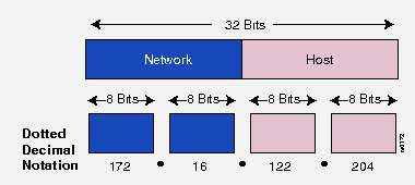
Each host on a TCP/IP network is assigned a unique 32-bit logical address. The IP address is divided into two main parts; the Network Number and the Host Number.
The network number identifies the network and must be assigned by the Internet Network Information Center (InterNIC) if the network is to be part of the Internet.
The host number identifies a host in the network and is assigned by the local network administrator.
The 32-bit IP address is grouped 8 bits at a time, each group of 8 bits is an octet. Each of the four octets are separated by a dot, and represented in decimal format, this is known as dotted decimal notation. Each bit in an octet has a binary weight (128, 64, 32, 16, 8, 4, 2, 1). The minimum value for an octet is 0 (all bits set to 0), and the maximum value for an octet is 255 (all bits set to 1).
The following figure shows the basic format of a typical IP address:

IP addressing supports three different commercial address classes; Class A, Class B, and Class C.
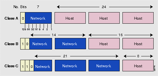
In a class A address, the first octet is the network portion, so the class A address of, 10.1.25.1, has a major network address of 10. Octets 2, 3, and 4 (the next 24 bits) are for the hosts. Class A addresses are used for networks that have more than 65,536 hosts (actually, up to 16,581,375 hosts!).
In a class B address, the first two octets are the network portion, so the class B address of, 172.16.122.204, has a major network address of 172.16. Octets 3 and 4 (the next 16 bits) are for the hosts. Class B addresses are used for networks that have between 256 and 65,536 hosts.
In a class C address, the first three octets are the network portion. The class C address of, 193.18.9.45, has a major network address of 193.18.9. Octet 4 (the last 8 bits) is for hosts. Class C addresses are used for networks with less than 254 hosts.
The class of address can be easily determined by examining the first octet of the address, and mapping that value to a class range in the table below:
The left-most (high-order) bits in the first octet indicate the network class.
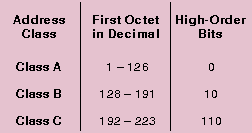
For example, given an IP address of 172.31.1.2, the first octet is 172. 172 falls between 128 and 191, so 172.31.1.2 is a Class B address.
Each of the commercial address classes has a set classfull network mask. The network mask defines which bits out of the 32 bit of the address are defined as the network portion and which are the host portion.
As stated above, a Class A address has the first octet as the network portion and the remaining 3 octets as the host portion. Therefore, a Class A network mask is defined as 255.0.0.0.
A Class B address has the first and second octets as the network portion and the third and fourth octets as the host portion. A Class B network mask is shown as 255.255.0.0.
A Class C address has the first, second, and third octet as the network portion and the last octet as the host portion. A Class C network mask is shown as 255.255.255.0.
The network mask is calculated by setting all bits to a value of 1 in the octets designated for the network portion and all bits to a value of 0 in the octets designated for the host portion.
The following figure summarizes the network and host portion of each address class:
All Classes of IP networks can be divided into smaller networks called subnetworks (or subnets).
Dividing the major class network is called subnetting. Subnetting provides network administrators with several benefits. It provides extra flexibility, makes more efficient use of network address utilization, and contains broadcast traffic because a broadcast will not cross a router.
Subnets are under local administration. As such, the outside world sees an organization as a single network, and has no detailed knowledge of the organization's internal network structure.
A given network address can be broken up into many subnetworks. For example, 172.16.1.0, 172.16.2.0, 172.16.3.0, and 172.16.4.0 are all subnets of the Class B network 171.16.0.0.
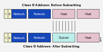
A subnet address is created by "borrowing" bits from the host field and designating them as the subnet field. The number of borrowed bits is variable and specified by the subnet mask.
The following figure shows how bits are "borrowed" from the host address field to create the subnet address field:
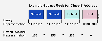
Subnet masks use the same format and representation technique as network mask format, the subnet mask has binary 1s in all bits specifying the network and subnetwork fields, and binary 0s in all bits specifying the host field.
The following figure shows a sample subnet mask:
When a router receives a packet, it makes a routing decision based on the destination address portion of the packet. It then looks up the destination address in its routing table. If the destination address is within a known network/subnetwork, the router forwards the packet to the next hop gateway for that destination network/subnetwork. Once the packet leaves the router, it is the responsibility of the next hop gateway to forward the packet to its final destination. If the router does not have the destination network in its routing table, it may forward the packet to a predetermined default gateway if configured and let the default gateway handle getting the packet to the destination network or it will drop the packet and inform the sending host that the network is not reachable.
The routing table is a list of networks that router knows about. It can learn these routes by 3 means: a routing protocol such as; RIP, IGRP, and OSPF, a static route that has been manually been set by a network administrator, or by being directly connected to that network on one of its interfaces.
The routing table will contain many pieces of information about the learned network, but the main information is the network address and the next hop gateway.
The network address can be either a full class network address or a subnetwork address, depending on the netmask being used. The next hop gateway is the ip address of the gateway to hand off the outbound packet to.
Keep in mind that all of the routers must know of a way to reach each other. The receiving host must have a path to get back to the sending host in order for data to pass.
Troubleshooting IP connectivity:
Before attempting to send any IP data through the router, verify that the router is aware of the destination network. A show ip route command will list all routes known to the Atlanta router and what interface is used to reach that specific network and the ip address of the next hop gateway. If there is not a specific route entry for the destination network, see if there is a default route setup that will forward the packet to the next router.
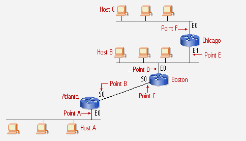
The following troubleshooting will refer to the following image as the network:
Once you have verified that an applicable route exists, there are two basic commands you can use on the router to verify IP connectivity; PING and TRACE.
The ping command uses the ICMP protocolís echo request and echo reply to verify the reachability and status of another host. Since both the echo request and reply travel in IP packets, successful replies from a host verifies that all major pieces of the transport layer are operational. A successful ping also ensures that the routers within the internetwork are functioning correctly and have correct routing tables.
Keep in mind that when pinging from a router, the router will use its closest interfaceís IP address as the source address when sending data. For example: Boston will use itís Serial 0 ip address when pinging Atlanta or any device on Atlantaís ethernet network. But Boston will use itís Ethernet 0 ip address whenever pinging Host B or Chicago.
To test ip connectivity from Atlanta, ping the routers local interfaces, Point A and B. This will verify that the Atlanta router and its interfaces are configured and functioning correctly. If point A or B fail, check the interface with a show interface command to verify that the interface is up and the line protocol is up, there may be a physical connection issue with the router or a configuration issue.
Next ping Host A from Atlanta. A successful ping will show that Host Aís TCP/IP software is installed correctly and the physical connection is working. If Host A does not respond to a ping, check the configuration of Host Aís TCP/IP software and network physical connection. Try to ping one of the other hosts on the same network segment. If other hosts respond to the ping, then there is a problem with Host A.
The next step is to ping Bostonís closest interface, Point C. This will verify that the interface connection between Atlanta and Boston is functioning correctly. If this ping fails, check Bostonís configuration. Verify the interface configuration. Have Boston ping itís own interface to verify that the interface will respond to pings.
Next ping Bostonís farside interface, Point D. This will verify that Atlanta knows of Bostonís ethernet network and that Bostonís interface is functioning fine. If the pings fail, first verify that Atlanta knows of Bostonís ethernet network via Bostonís near side interface, Point C. Also verify that Boston can ping itís own interfaces to ensure that they are up and functioning correctly.
Next, ping Host B from Atlanta. A successful ping to Host B will verify that Host B is configured correctly. If Host B fails to respond to the ping, chances are there is a configuration problem on Host B. Try and ping Host B from Boston. If this fails, then check Host Bís TCP/IP software configuration and physical connection. If Boston can ping Host B but Atlanta can not, verify that Host B is pointing to either Boston or Chicago as the default gateway and that the default gateway knows of a route back to Atlantaís serial network.
Next ping Chicagoís near side ethernet port, Point E. This will verify that Chicago knows that Atlantaís serial network is reachable via Bostonís ethernet interface, Point D. If Atlanta is unable to ping Chicagoís near side ethernet ip address, there may be a configuration error on Chicago. Ping Chicagoís near side ethernet port, Point E, from Boston to verify it will respond to pings. If Boston can ping Chicagoís near side ethernet port and Atlanta can not, verify that Chicago has a route in itís routing table that knows how to get back to Atlanta via Bostonís ethernet port, Point D.
Next ping Chicagoís far side ethernet port, Point F. If this ping fails, verify that Atlanta and B know how to get to Chicagoís ethernet 1 network via Chicagoís near side, Point E. Ping Chicagoís far side ethernet port from Boston. If this fails, ping Chicagoís far side ethernet port from Chicago to verify the interface will respond to pings.
Now ping Host C from Atlanta. This will test the configuration of Host Cís TCP/IP software configuration and physical connection. If this ping fails, ping Host C from Chicago. If Host C fails to respond to Chicagoís ping, then verify Host Cís TCP/IP software configuration and physical connection. If Host C will respond to Chicagoís pings but not to Atlantaís pings, verify that Host C is pointing to Chicagoís Ethernet 1 interface, Point F, as the default gateway.
Now ping Host C from Host A. If Host C responds to Host Aís pings, then there is full ip connectivity in the network. All devices should be able to ping each other. If Host A is unable to ping Host C, verify that Host A has Atlantaís Ethernet 0 port, Point A, as the default gateway. Also verify that Chicago knows Atlantaís ethernet network is reachable via Bostonís Ethernet 0 interface, Point D.
Traceroute is used to display the gateways traversed to reach a destination host. Traceroute uses UDP data packets with incrementing TTL, time-to-live, values and an invalid port number to build the traceroute list of gateways.
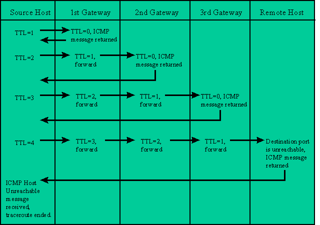
The host originating the traceroute starts out by sending a data packet with a destination address of the remote host and a TTL value of 1. The first gateway that receives the packet, will decrease the TTL value by 1. Since the TTL value is now 0, the gateway sends back an ICMP "Timeout Exceeded" message to the originating host. The originating host then adds that gateway to the traceroute list and sends out another data packet with a TTL value of 2. The first gateway will receive the packet and decrease the TTL value by 1 and forward the packet to the next gateway. When that gateway receives the packet, it decreased the TTL value by 1. Now the TTL value is 0 and the gateway sends back an ICMP Timeout Exceeded message back to the originating host. When the originating host receives the ICMP message, it adds that gateway to the traceroute list and sends out another data packet with a TTL value of 3. This process continues, each time the TTL value is 0, the gateway replies with an ICMP message and the originating host adds it to the list and sends out another data packet with an increased TTL value.
Once the destination host receives the data packet, it sees that the port number is invalid and sends back an ICMP "Unreachable Port" message back to the originating host. When the originating host receives this message, it knows that the host has been reached and ends the traceroute.
Here is a graphical flow of a typical traceroute:
Trace route is helpful in locating routing issues on a distant gateway. If the local routing tables are correct on routers locally administered, distant routers under another administration may be the cause of misrouted or dropped data packets. Traceroute will give a general location of where the packet is getting lost. Remember, once a packet is handed to the next gateway, it is that gatewayís responsibility to see to it that the packet continues on correctly to the final destination.